After Hours Shipping

Real Time Order Tracking

Flexible Delivery Options

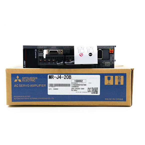
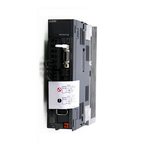
| Model: | MR-J4-_(-RJ) | 10B | 20B | 40B | 60B | 70B | 100B | 200B | 350B | 500B | 700B | 11KB | 15KB | 22KB | |||
| Output | Rated voltage | 3-phase 170 V AC | |||||||||||||||
| Rated current | [A] | 1.1 | 1.5 | 2.8 | 3.2 | 5.8 | 6.0 | 11.0 | 17.0 | 28.0 | 37.0 | 68.0 | 87.0 | 126.0 | |||
|
Main circuit power supply input |
Voltage/ Frequency |
At AC input |
3-phase or 1-phase 200 V AC to 240 V AC, 50 Hz/60 Hz |
3-phase or 1-phase 200 V AC to 240 V AC, 50 Hz/60
Hz (Note 13) |
3-phase 200 V AC to 240 V AC, 50 Hz/60 Hz |
||||||||||||
| At DCinput
(Note 16) |
283 V DC to 340 V DC | ||||||||||||||||
| Rated current (Note 11) | [A] | 0.9 | 1.5 | 2.6 | 3.2(Note 6) | 3.8 | 5.0 | 10.5 | 16.0 | 21.7 | 28.9 | 46.0 | 64.0 | 95.0 | |||
|
Permissible voltage fluctuation |
At AC
input |
3-phase or 1-phase 170 V AC to 264 V AC | 3-phase or 1-phase 170 V AC to 264 V AC (Note 13) |
3-phase 170 V AC to 264 V AC |
|||||||||||||
| At DCinput
(Note 16) |
241 V DC to 374 V DC | ||||||||||||||||
| Permissible frequency fluctuation | Within ±5% | ||||||||||||||||
| Power supply capacity[kVA] | Refer to section 10.2. | ||||||||||||||||
| Inrush current | [A] | Refer to section 10.5. | |||||||||||||||
|
Control circuit power supply input |
Voltage/ Frequency | At ACinput | 1-phase 200 V AC to 240 V AC, 50 Hz/60 Hz | ||||||||||||||
| At DCinput
(Note 16) |
283 V DC to 340 V DC | ||||||||||||||||
| Rated current | [A] | 0.2 | 0.3 | ||||||||||||||
| Permissible voltage fluctuation | At ACinput | 1-phase 170 V AC to 264 V AC | |||||||||||||||
| At DCinput
(Note 16) |
241 V DC to 374 V DC | ||||||||||||||||
| Permissible frequency fluctuation | Within ±5% | ||||||||||||||||
| Power consumption | [W] | 30 | 45 | ||||||||||||||
| Inrush current | [A] | Refer to section 10.5. | |||||||||||||||
| Interface power supply | Voltage | 24 V DC ± 10% | |||||||||||||||
| Current capacity | [A] | 0.3 (including CN8 connector signals) (Note 1) | |||||||||||||||
| Control method | Sine-wave PWM control, current control method | ||||||||||||||||
| Dynamic brake | Built-in | External option (Note 9, 12) | |||||||||||||||
| SSCNET III/H communication cycle(Note 8) | 0.222 ms, 0.444 ms, 0.888 ms | ||||||||||||||||
| Fully closed loop control | Compatible (Note 7) | ||||||||||||||||
| Scale measurement function | Compatible (Note 10) | ||||||||||||||||
| Load-side encoder interface (Note 5) | Mitsubishi Electric high-speed serial communication | ||||||||||||||||
| Communication function | USB: connection to a personal computer or others (MR Configurator2-compatible) | ||||||||||||||||
| Encoder output pulses | Compatible (A/B/Z-phase pulse) | ||||||||||||||||
| Analog monitor | Two channels | ||||||||||||||||
|
Protective functions |
Overcurrent shut-off, regenerative overvoltage shut-off, overload shut-off (electronic thermal), servo motor overheat protection, encoder error protection, regenerative error protection, undervoltage protection, instantaneous power failure protection, overspeed protection, error excessive protection, magnetic pole detection protection, and linear servo control fault protection | ||||||||||||||||
| Functional safety | STO (IEC/EN 61800-5-2) | ||||||||||||||||
|
Safety performance |
Standards certified by CB (Note 14) | EN ISO 13849-1 Category 3 PL e, IEC 61508 SIL 3, EN 62061 SIL CL3, EN 61800-5-2 | ||||||||||
| Response performance | 8 ms or less (STO input off → energy shut off) | |||||||||||
| Test pulse input (STO) (Note 3) | Test pulse interval: 1 Hz to 25 HzTest pulse off time: Up to 1 ms | |||||||||||
| Mean time to dangerous failure (MTTFd) | MTTFd ≥ 100 [years] (314a) | |||||||||||
| Diagnostic coverage (DC) | DC = Medium, 97.6 [%] | |||||||||||
| Average probability of dangerous failures per hour (PFH) | PFH = 6.4 × 10⁻⁹ [1/h] | |||||||||||
| Compliance with global standards | CE marking | LVD: EN 61800-5-1EMC: EN 61800-3
MD: EN ISO 13849-1, EN 61800-5-2, EN 62061 |
||||||||||
| UL standard | UL 508C | |||||||||||
| Structure (IP rating) | Natural cooling, open (IP20) | Force cooling, open (IP20) | Force cooling, open (IP20) (Note 4) | |||||||||
| Close mounting (Note 2) | 3-phase power supply input | Possible | Impossible | |||||||||
| 1-phase power supply input | Possible | Impossible | ||||||||||
|
Environment |
Ambienttemperature | Operation | 0 ˚C to 55 ˚C (non-freezing) | |||||||||
| Storage | -20 ˚C to 65 ˚C (non-freezing) | |||||||||||
| Ambient humidity | Operation | 5 %RH to 90 %RH (non-condensing) | ||||||||||
| Storage | ||||||||||||
| Ambience | Indoors (no direct sunlight),free from corrosive gas, flammable gas, oil mist, dust, and dirt | |||||||||||
| Altitude | 2000 m or less above sea level (Note 15) | |||||||||||
| Vibration resistance | 5.9 m/s2, at 10 Hz to 55 Hz (directions of X, Y and Z axes) | |||||||||||
| Mass [kg] | 0.8 | 1.0 | 1.4 | 2.1 | 2.3 | 4.0 | 6.2 | 13.4 | 18.2 | |||
Note 1. 0.3 A is the value applicable when all I/O signals are used. The current capacity can be decreased by reducing the number of I/O points.
6 The rated current is 2.9 A when the servo amplifier is used with UL or CSA compliant servo motor.