After Hours Shipping

Real Time Order Tracking

Flexible Delivery Options

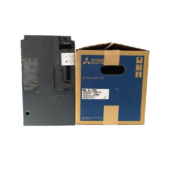
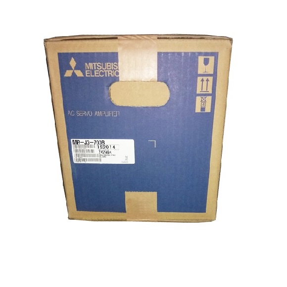
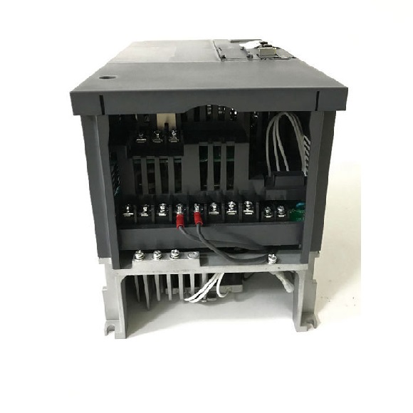
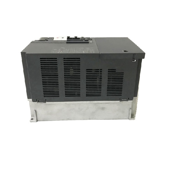
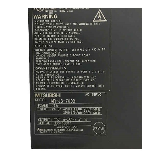
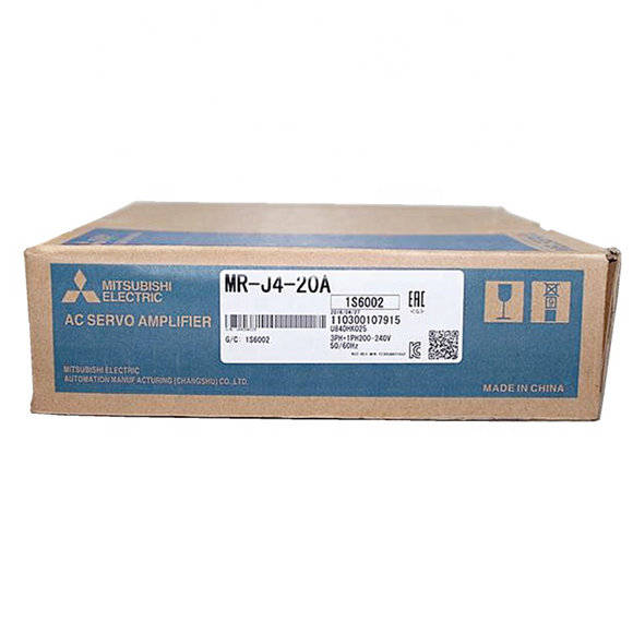
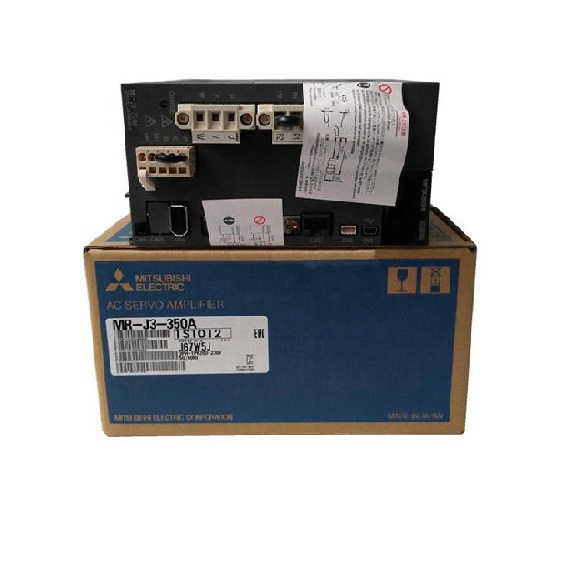
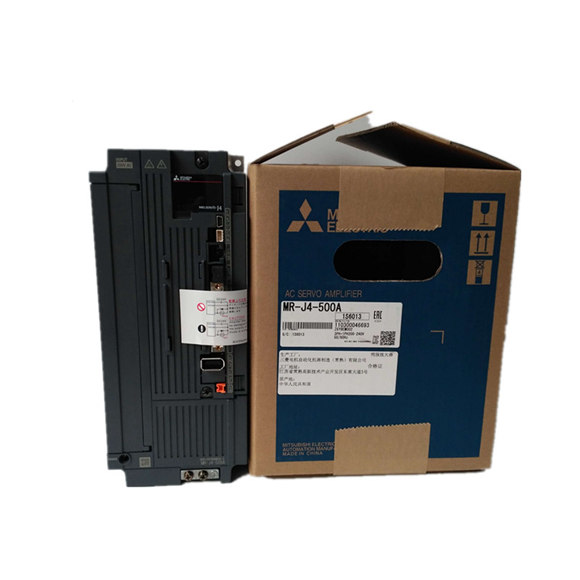
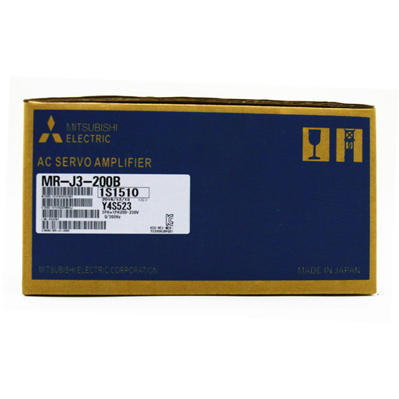
Mitsubishi Servo Drive MR-J3 7.5KW MR-J3-700BMR-J3-A Servo Amplifier Specifications 100/200V 22kW or Smaller
| Servo Amplifier Model MR-J3- | 10A | 20A | 40A | 60A | 70A | 100A | 200AN | 350A | 500A | 700A | 11KA | 15KA | 22KA | 10A1 | 20A1 | 40A1 | |
| Stocked Item | S | S | S | S | S | S | S | S | S | S | S | – | – | S | S | S | |
| Main Circuit Power Supply | Voltage/Frequency (*1, *2) | 3-phase 200 to 230VAC 50/60Hz or1-phase 200 to 230VAC 50/60Hz (*10) | 3-phase 200 to 230VAC 50/60Hz | 1-phase 100 to 120VAC 50/60Hz | |||||||||||||
| Permissible Voltage Fluctuation | For 3-phase 200 to 230VAC: 3-phase 170 to 253VACFor 1-phase 200 to 230VAC: 1-phase 170 to 253VAC | 3-phase 170 to 253VAC | 1-phase 85 to 132VAC | ||||||||||||||
| Permissible Frequency Fluctuation | ±5% maximum | ||||||||||||||||
| Control Circuit Power Supply | Voltage/Frequency | 1-phase 200 to 230VAC 50/60Hz (*10) | 1-phase 200 to 230VAC 50/60Hz | 1-phase 100 to 120VAC 50/60Hz | |||||||||||||
| Permissible Voltage Fluctuation | 1-phase 170 to 253VAC | 1-phase 85 to 132VAC | |||||||||||||||
| Permissible Frequency Fluctuation | ±5% maximum | ||||||||||||||||
| Power Consumption (W) | 30 | 45 | 30 | ||||||||||||||
| Interface Power Supply | 24VDC ±10% (required current capacity: 300mA (*7)) | ||||||||||||||||
| Regenerative Resistor/ Tolerable Regenerative Power (W) (*3, *4) | Built-in Regenerative Resistor | – | 10 | 10 | 10 | 20 | 20 | 100 | 100 | 130 | 170 | – | – | – | – | 10 | 10 |
| External Regenerative Resistor (Standard Accessory) (*5, *6) | – | – | – | – | – | – | – | – | – | – | 500(800) | 850(1300) | 850(1300) | – | – | – | |
| Control System | Sine-wave PWM control/current control system | ||||||||||||||||
| Dynamic Brake | Built-in (*8, *13) | External option | Built-in (*8, *13) | ||||||||||||||
| Safety Features | Overcurrent shutdown, regeneration overvoltage shutdown, overload shutdown (electronic thermal), Servo Motor overheat protection, encoder fault protection, regeneration fault protection, undervoltage/sudden power outage protection, overspeed protection, excess error protection | ||||||||||||||||
| Position Control Mode | Maximum Input Pulse Frequency | 1Mpps (when using differential receiver), 200kpps (when using open collector), (4Mpps) (*11) | |||||||||||||||
| Positioning Feedback Pulse | Resolution per encoder/Servo Motor rotation: 262144 p/rev | ||||||||||||||||
| Command Pulse Multiple | Electronic gear A/B multiple, A: 1 to 1048576, B: 1 to 1048576, 1/10 < A/B < 2000 | ||||||||||||||||
| Positioning Complete Width Setting | 0 to ±10000 pulses (command pulse unit) | ||||||||||||||||
| Excess Error | ±3 rotations | ||||||||||||||||
| Torque Limit | Set by parameters or external analog input (0 to +10VDC/maximum torque) | ||||||||||||||||
| Speed Control Mode | Speed Control Range | Analog speed command 1:2000, internal speed command 1:5000 | |||||||||||||||
| Analog Speed Command Input | 0 to ±10VDC/rated speed (possible to change the speed in 10V using the parameter No. PC12.) (*12) | ||||||||||||||||
| Speed Fluctuation Rate | ±0.01% maximum (load fluctuation 0 to 100%) 0% (power fluctuation ±10%) ±0.2% maximum (ambient temperature 25°C±10°C (59°F to 95°F)), when using analog speed command | ||||||||||||||||
| Torque Limit | Set by parameters or external analog input (0 to +10VDC/maximum torque) (*12) | ||||||||||||||||
| Torque Control Mode | Analog Torque Command Input | 0 to ±8VDC/maximum torque (input impedance 10 to 12kΩ) (*12) | |||||||||||||||
| Speed Limit | Set by parameters or external analog input (0 to ±10VDC/rated speed) | ||||||||||||||||
| Structure | Self-cooling open (IP00) | Fan cooling open (IP00) | Self-cooling open (IP00) | ||||||||||||||
| Environment | Ambient Temperature (*6, *9) | 0 to 55°C (32 to 131°F) (non-freezing), storage: -20 to 65°C (-4 to 149°F) (non-freezing) | |||||||||||||||
| Ambient Humidity | 90% RH maximum (non-condensing), storage: 90% RH maximum (non-condensing) | ||||||||||||||||
| Atmosphere | Indoors (no direct sunlight); no corrosive gas, inflammable gas, oil mist or dust | ||||||||||||||||
| Elevation | 1000m or less above sea level | ||||||||||||||||
| Vibration | 5.9m/s² maximum | ||||||||||||||||
| Weight kg (lb) | 0.8(1.8) | 0.8(1.8) | 1.0(2.2) | 1.0(2.2) | 1.4(3.1) | 1.4(3.1) | 2.1(4.6) | 2.3(5.1) | 4.6(10) | 6.2(14) | 18(40) | 18(40) | 19(42) | 0.8(1.8) | 0.8(1.8) | 1.0(2.2) | |