After Hours Shipping

Real Time Order Tracking

Flexible Delivery Options

| Model
Item |
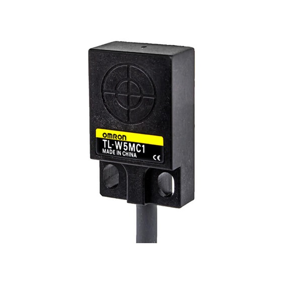
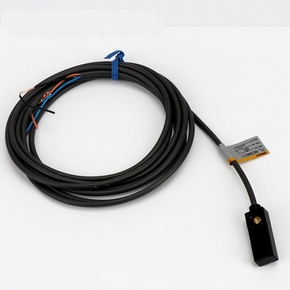
TL-W1R5MC1 TL-W1R5MB1 | TL-W3MC@ TL-W3MB@ | TL-W5MC@ TL-W5MB@ | TL-W5E1, TL-W5E2 TL-W5F1, TL-W5F2 | TL-W20ME1 TL-W20ME2 |
| Sensing distance | 1.5 mm ±10% | 3 mm ±10% | 5 mm ±10% | 20 mm ±10% | |
| Set distance | 0 to 1.2 mm | 0 to 2.4 mm | 0 to 4 mm | 0 to 16 mm | |
| Differential travel | 10% max. of sensing distance | 1% to 15% of sensing distance | |||
| Detectable object | Ferrous metal (The sensing distance decreases with non-ferrous metal. Refer to Engineering Data on page 5.) | ||||
| Standard sensing object | Iron,
8 ´ 8 ´ 1 mm |
Iron,
12 ´ 12 ´ 1 mm |
Iron, 18 ´ 18 ´ 1 mm | Iron, 50 ´ 50 ´ 1 mm | |
| Response frequency | 1 kHz min. | 600 Hz min. | 500 Hz min. | 300 Hz min. | 40 Hz min. |
| Power supply volt- age (operating voltage range) |
12 to 24 VDC (10 to 30 VDC), ripple (p-p): 10% max. |
12 to 24 VDC (10 to 30
VDC), ripple (p-p): 20% max. |
12 to 24 VDC (10 to 30
VDC), ripple (p-p): 10% max. |
||
| Current consumption | 15 mA max. at 24 VDC (no-load) | 10 mA max.
at 24 VDC (no-load) |
15 mA max.
at 24 VDC (no-load) |
8 mA at 12 VDC,
15 mA at 24 VDC |
|
|
Load current |
TL-W1R5MC1/-W3MC@: NPN open collector 100 mA max. at 30 VDC max. TL-W1R5MB1/-W3MB@: PNP open collector 100 mA max. at 30 VDC max. |
TL-W5MC@:
NPN open collector 50 mA max. at 12 VDC (30 VDC max.) 100 mA max. at 24 VDC (30 VDC max.) TL-W5MB@: PNP open collector 50 mA max. at 12 VDC (30 VDC max.) 100 mA max. at 24 VDC (30 VDC max.) |
200 mA |
100 mA max. at 12 VDC 200 mA max. at 24 VDC |
|
| Residual voltage |
1 V max. (under load current of 100 mA with cable length of 2 m) |
2 V max. (under load cur- rent of 200 mA with cable length of 2 m) | 1 V max. (under load current of 200 mA with cable length of 2 m) | ||
| Indicators | Detection indicator (red) | ||||
| Operation mode (with sensing ob- ject approaching) | NO | B1/C1 Models: NO B2/C2 Models: NC | E1/F1 Models: NO E2/F2 Models: NC | ||
| Refer to the timing charts under I/O Circuit Diagrams on page 6 for details. | |||||
| Protection circuits | Reverse polarity protection, Surge suppressor | ||||
| Ambient temperature range | Operating/Storage: -25 to 70°C (with no icing or condensation) * | ||||
| Ambient humidity range | Operating/Storage: 35% to 95% (with no condensation) | ||||
| Temperature influence | ±10% max. of sensing distance at 23°C in the temperature range of -25 to 70°C | ||||
|
Voltage influence |
±2.5% max. of sensing distance at rated voltage in the rated voltage ±10% range | ±2.5% max. of sensing
distance at rated volt- age in the rated voltage ±20% range |
±2.5% max. of sensing distance at rated voltage in the rated voltage ±10% range | ||
| Insulation resistance | 50 MΩ min. (at 500 VDC) between current-carrying parts and case | ||||
| Dielectric strength | 1,000 VAC, 50/60 Hz for 1 minute between current-carrying parts and case | ||||
| Vibration resistance | Destruction: 10 to 55 Hz, 1.5-mm double amplitude for 2 hours each in X, Y, and Z directions | ||||
|
Shock resistance |
Destruction: 500 m/s2 3 times each in X, Y, and Z directions |
Destruction: 500 m/s2 10 times each in X, Y, and Z directions | |||
| Degree of protection | IEC 60529 IP67, in-house standards: oil-resistant * | ||||
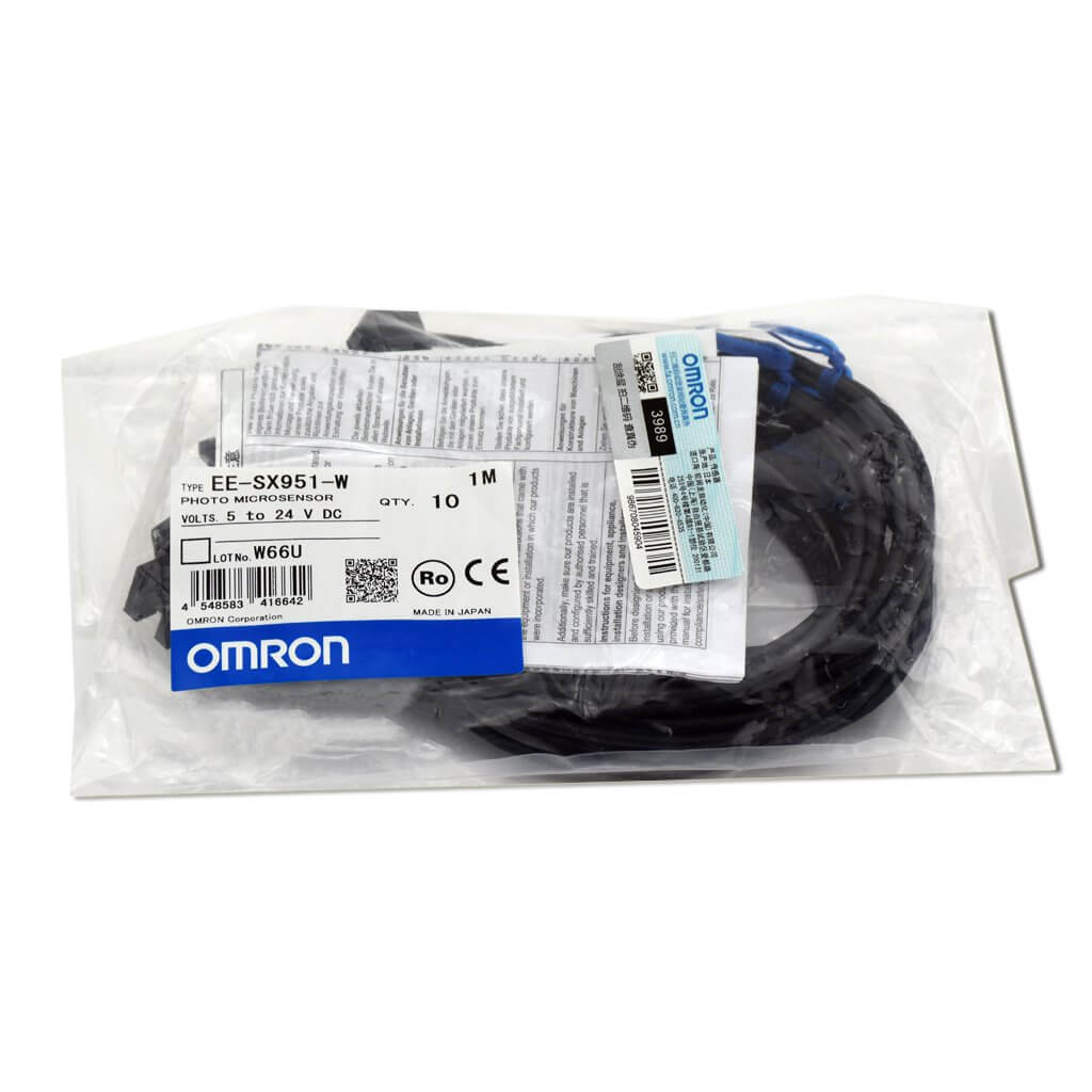
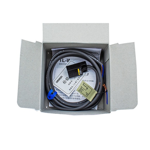
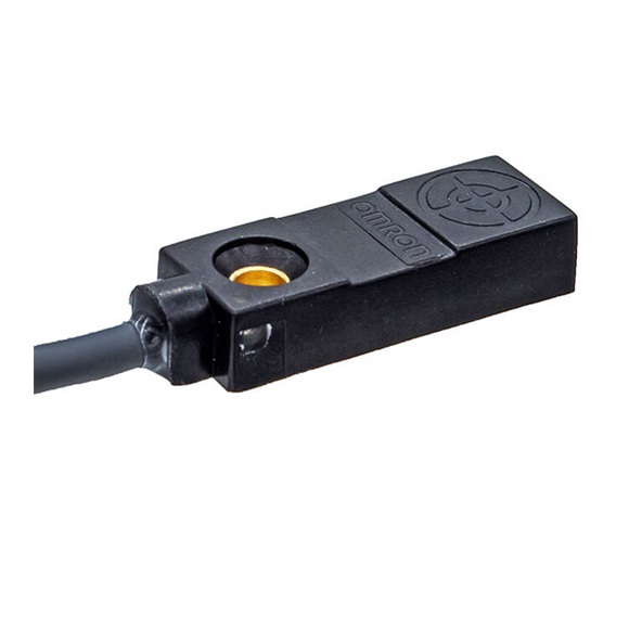
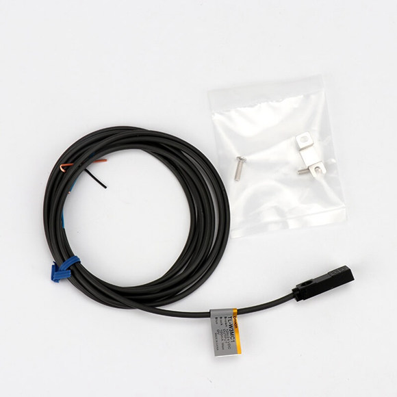
| Connection method | Pre-wired Models (Standard cable length: 2 m) | ||||
| Weight (packed state) | Approx. 70 g | Approx. 80 g | Approx. 100 g | Approx. 210 g | |